
Filling technology selection
Monoblock vs Separate Filling Machines
Choose a rinsing-filling-capping monoblock when the three operations should be specified and coordinated as one package. Review separate machines when retaining an existing operation or adapting a constrained layout has measurable value. Compare transfers, access, stop/restart behavior and integration responsibility—not footprint alone. A 3-in-1 monoblock is not a complete beverage production line.
Request a Machine Configuration ReviewMachine selection and configuration
Compare the Whole Operating Boundary
| Decision | Rinser-filler-capper monoblock | Separate operations |
|---|---|---|
| Transfers | Coordinated transfers inside the grouped operations; confirm actual handling parts. | Define each conveyor handoff, bottle stability requirement, sensor and control owner. |
| One operation stops | A fault may stop the grouped process. Demonstrate its stop and restart sequence. | Independent drives do not guarantee independent production; buffers and interlocks determine what continues. |
| Product exposure | Review the protection and path from filling to closure. | Assess open-bottle exposure and permitted time to closure. Do not add accumulation without process approval. |
| Service and cleaning | Shared guards and structures need a defined isolation and access plan. | Individual access may help; extra connections and transfers still require cleaning and maintenance. |
| Floor space | Include cap supply, utilities, guards and service clearance. | Include the same boundary plus connecting conveyors, not just bare machine dimensions. |
| Retained equipment | Check whether an existing serviceable rinser or capper becomes redundant. | Retain equipment only after matching package, process, controls and accepted output. |
| Responsibility | Name the integration owner and exclusions even with one main-machine supplier. | Name who designs, wires, tests and accepts each handoff between suppliers. |
Machine selection and configuration
A Conveyor Buffer Buys Time, Not Extra Throughput
Illustrative closed-bottle conveyor calculation—not a recommendation to accumulate open or hot-filled product. Buffer cover = usable bottle positions ÷ arrival rate. Actual capacity depends on spacing, sensors, controls and permitted accumulation.
| Condition | Arithmetic or limit | Procurement implication |
|---|---|---|
| 120 usable positions at 6,000 BPH | 6,000 ÷ 60 = 100 bottles/minute; 120 ÷ 100 = 1.2 minutes | About 72 seconds of idealized downstream-stop coverage, not unlimited independence. |
| Downstream is slower on average | Average discharge remains below average arrival | The buffer eventually fills; accumulation cannot remove a sustained bottleneck. |
| Restart after the buffer fills | Recovery needs spare downstream capacity and an agreed sequence | Test blocked/starved signals and restart behavior during acceptance. |
Machine selection and configuration
Use One Scope Sheet for Both Alternatives
- Mark rinsing, filling and capping as new, retained, optional or excluded.
- Attach bottle/neck/cap drawings, layout and conveyor elevations.
- Identify each transfer, cleaning/utility connection and controls handoff.
- Mark usable buffers and restrictions on exposure, holding and accumulation.
- Include service clearance, change parts, safety isolation and FAT/site acceptance owners.
Machine selection and configuration
Continue Your Machine Selection
New PET water filling section
Compare an XGF proposal with the same beverage, bottle, cap, rinse basis and accepted-output requirement.
New PET water filling sectionKeep a capable existing capper
Check filled-bottle stability, closure timing and fault/restart interlocks before assuming the old unit can stay.
Keep a capable existing capperSpecify the 3-in-1 supply scope
Separate the rinser-filler-capper from beverage preparation, bottle blowing, labeling and packing.
Specify the 3-in-1 supply scopeCatalog equipment evidence
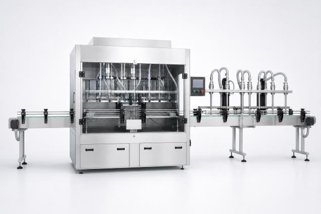
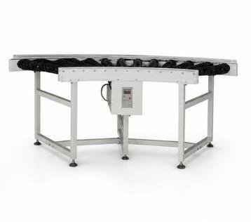
Integrated and Separate Equipment Boundaries
A monoblock reduces some transfers while separate equipment can change access, ownership and changeover. Confirm every interface in the proposal.

Engineering decision guide
Continue the buyer decision path
Use these pages in sequence to understand, compare, plan, choose and prepare a project-specific request.
-
Beverage Filling Machines
Compare filling machine families by beverage behavior, filling basis, package handling and the interfaces required around the filler.
-
Monoblock vs Separate Filling Machines
Compare a monoblock with separate machines through transfer control, access, changeover, retained equipment and project boundaries.
-
Filling Machine Technical Specification Checklist
Create one controlled specification covering duty, formats, output, interfaces, utilities, materials, controls, tests, documents and exclusions.
-
Filling Machine Selector
Generate a preliminary technology route from beverage, process, package and output inputs, then verify open assumptions with an engineer.
-
Request a Filling Machine Recommendation
Send a structured machine brief with the known product, package, output, site and project facts, while marking unknowns openly.
Buyer questions
Frequently asked questions
When can separate machines be preferable to a monoblock?
Separate equipment may fit a retained layout, isolated replacement or a project with clearly owned transfer and control interfaces, subject to the application.
Does a monoblock remove every transfer and control interface?
No. It reduces transfers between integrated operations but still has product, container, cap, utility, infeed, discharge, safety, controls and maintenance boundaries.
Can a monoblock replace one machine in an existing line?
Only after the retained equipment, conveyor geometry, line speed, controls, utilities, floor space and shutdown plan are measured. A brochure layout is not enough to establish fit.
Can a monoblock also be a rotary filling machine?
Yes. Monoblock describes combined operations; rotary describes container motion. State the operations, motion, filling principle and package basis separately in the specification.
Last reviewed:
Next machine-selection action
Request a Configuration Based on Your Production Task
Send the beverage, bottle/cap drawings, production schedule, target accepted output and equipment you plan to retain. Allot Tech can review the machine scope and items requiring confirmation.